This is an old revision of the document!
Table of Contents
Home Brewing
Malt mill
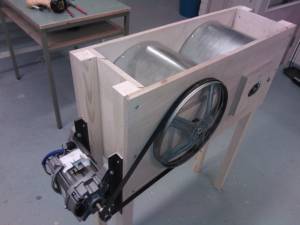
This is a report of a DIY malt mill project. The target is to achieve close to professional result in milling malt. There are commercial mills available for hobbyists, like Corona, Crankandstein, Monster Mill and JSP Maltmill. Problem with all of those competitors is that they result too fine granularity for optimal mash lautering.
The author has already experience in costructing a motorized malt mill with Crankandstein model 3D roller unit.
Mechanics
This section is under construction as the mechanics is still under construction.
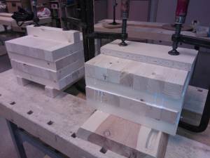
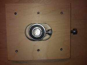
Wooden rollers with massive glued laminated timber core (pine) and plywood endings (15mm birch). First raw cut with band saw..
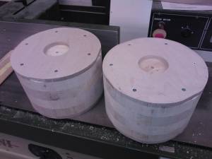
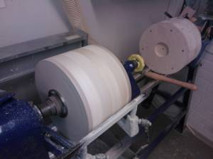
..then rotary cutting in lathe and drilling 22mm center hole.
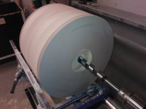
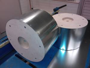
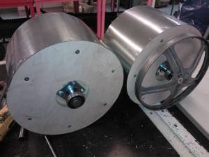
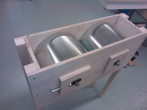
Rollers plated with metal sheet (0.5mm galvanized steel).
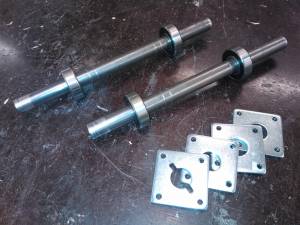
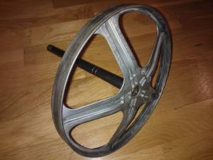
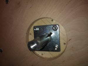
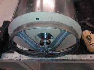
Shaft, ball bearings and pulley.
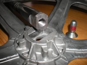
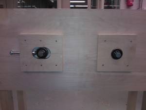
Spline attach of shaft and roller.
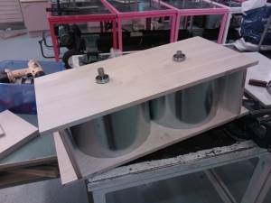
Framework
Assembly
Ball bearings
Motor
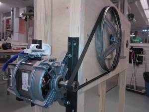
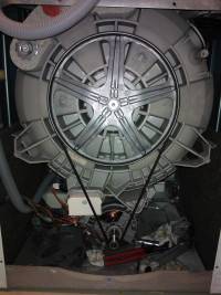
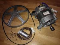
Motor and power transmission are taken from an old washing machine, which I exchanged to a bottle of wine. The washer was fully operational, except having broken shock absorbers, thus the owner replaced it by a brand new one.
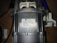
The washer is AEG brand ÖKO_LAVAMAT Belle update, where the term “update” means the electronics can not be re-used for DIY project (highly integrated, microcontroller driven). Motor, belt, pulley and AC noise filter were salved for further use.
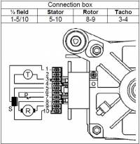
The washer has a universal motor rated 230VAC 50Hz (European mains). The motor is called universal, as it can be driven with both AC and DC. Motors from many different manufacturers are specified in this document Electrolux Service Bulletin. The motor of the AEG washer, manufactured by FHP-Motors, was also included in the list, and has the following connector pinout.
In order to run the motor, rotor and stator are connected in series. AC phase or DC supply voltage is connected to either end of the split stator coil (pin 5 or 10), depending on wanted direction of rotation. For series installation, the stator pin 1 is connected to either one of rotor brushes (pin 8 or 9). The other rotor pin (9 or 8) is connected to neutral (AC) or to ground (DC).
Universal motors are not synchronous, thus RPM depends on load and power given. In order to run the motor at certain constant velocity, tachometric feedback is needed for motor power controller. These motors have integrated tachometric generator, providing sine wave having amplitude and frequency proportional to angular velocity.
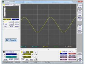
The oscilloscope snapshot illustrates tachometer output when the motor is driven at 12VDC and without external load. Amplitude (peak-to-peak) is about 15 volts and periodic time 4,5 milliseconds, meaning frequency of 220 Hz. As the FHP tachogenerator has 8 poles, the frequency equals to 3300 RPM.
Electronics
Universal motor is not synchronous. When connected directly to mains, the motor will gain speed until ball bearing failure or some other damage occurs. Electronic power controller is needed when this type of motor is in use.
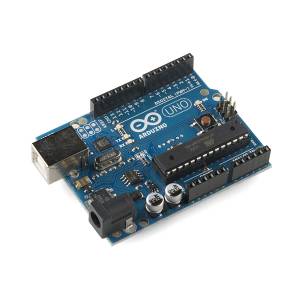
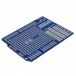
Arduino Uno board has Atmel's ATmega328P microcontroller, which is suitable for the simple motor speed control application. Prototyping shield makes it easy to construct your own electronic circuits.
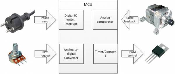
Required MCU peripherals are:
- Externally interrupted DIO for zero-cross detection
- Timer/Counter for PWM generation
- Analog comparator for sensing tachmeter feedback
- Analog to digital converter (ADC) for user input (optional)
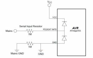
Single phase AC motors are PWM-driven with Phase fired controllers, which are sort of dimmers. Triacs are commonly used to switch the power. Mains voltage zero-cross detection is required for synchronization of the closed-loop phase angle control. Atmel's application note AVR182: Zero Cross detector describes super-simple circuit consisting only two 1 megaohm resistors.
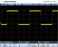
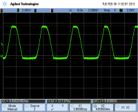
The oscilloscope screenshot shows waveform measured from PD2/Ext.Int0 input pin. The effect of internal clamp diodes is clearly visible, the signal voltage over- and undershoot by 0.5V, which is the diode forward voltage drop, causing signal high +5.5V (Y2) and signal low -0.5V (Y1).
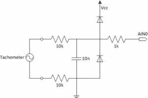
The same principle is applied to tachometer input, except using analog comparator instead of digital IO pin. Whereas amplitude of mains voltage is rather constant, the tachometer amplitude may vary from just a few volts up to 100 volts (open circuit). This makes it more complex to reliable detect the frequency.
In order to sense amplitude less than 5 volts, analog comparator is used. According to experiments, tachometer signal is more prone to interference, and need some filtering. RC-filter with 200k series resistance and 1nF capacitor was tested, but it didn't attenuated noise enough.
As the designed current limit of internal clamp diodes is only 1mA, external clamp diodes are needed in order to increase current. With external diodes it is possible to decrease series resistance and increase capacitor size, to have better filtering behavior still maintaining the same -3dB cut-off frequency of 796 Hz, as f_c = 1 / (2πRC). Small series resistor in MCU input ensures current goes thru external diodes, instead of internal ones.
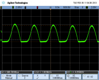
The oscilloscope snapshots below show input waveform in analog comparator pin at 220 and 1000 Hz frequency with 20 Vp-p amplitude (maximum provided by the signal generator used).
In reality, the tachogen generates bigger amplitude at 1000 Hz, thus not as much attenuation is expected as is presented in the screenshot. If analog comparator uses internal 1.1V bandgap reference voltage of the MCU, even the attenuated signal is strong enough to reliable trigger the interrupt.
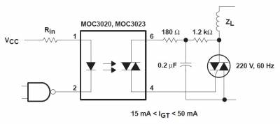
AC power driver circuit typically consists of optocoupled phototriac driver and power triac. Motors are inductive load, thus gate filtering is needed in order to avoid miss-fire, meaning unintentional triac activation due to inducted peak voltages.
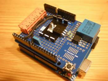
The whole circuit is assembled to an Arduino prototyping shield. Key components are triac BT137-800 12A (TO220 with heat sink in the middle), optocoupler MOC3023 (DIP-6 at right), capacitor 220nF @ 250VAC (big blue at right), sensing series resistors (black “wires” next to orange connector, resistors protected with heat sink sleeve), tacho-input noise filtering capacitor 1nF (small blue one), and orange connector for mains, motor and tachometer.
Arduino pin-mapping:
- Digital 2 : PD2/INT0 - Zero-cross sensing / External interrupt
- Digital 7 : PD7/AIN1 - Tachometer input / Analog comparator
- Digital 9 : PB1/OC1A - PWM control output / Timer/counter1
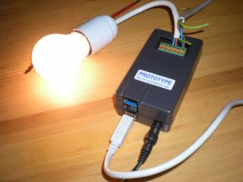
NB! The circuit has dangerous 240 VAC mains voltage exposed to human contact. Whenever connecting to mains voltage, have the circuit covered with proper plastic chassis. In the picture above, a box specially made for Arduino is used. These instructions are intended for experienced person only, qualified for mains voltage installations.
Software
When varying load occurs, a closed-loop control algorithm is needed to maintain constant velocity.
The software is implemented with Arduino IDE. However, Arduino libraries are not used for peripheral access, but direct access to interrupt routines is used for superior control of execution.
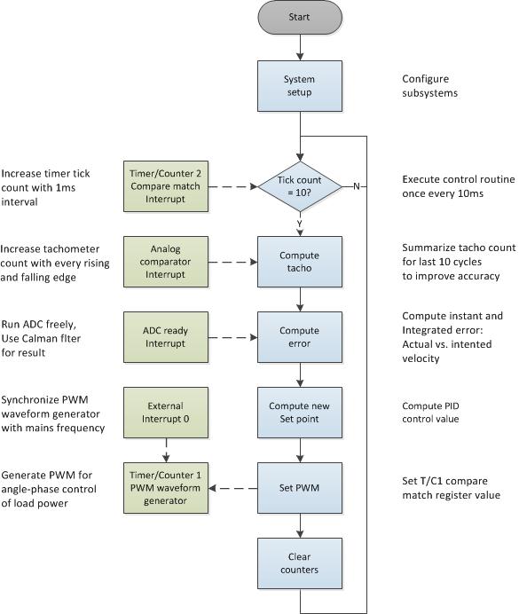
The PID control algorithm is executed with 100 Hz frequence. The execution occurs in main routine context (blue boxes). Peripheral drivers are executed in interrupt context (green boxes). Data is exhanged in between main and interrupt context in global volatile variables.
PID Control
PID control algorithm is executed with 10ms interval (100 times per second). In this implementation, only proportional and integral parameters are used (PI-controller).
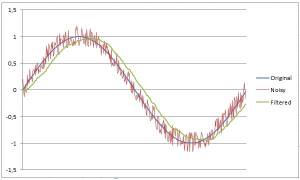
Desired process Set-Point (SP) is get from analog input, and digitally filtered with Kalman filter. The simulation presents random noise (-0.2..0.2) added a top sinusoidal signal (-1..1). The noisy data is filtered with Kalman filter weighting old value by factor of 15, and new value by factor of 1. The original waveform is preserved pretty well, though some phase shift (delay) exists.
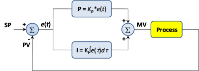
Measured process variable PV comes from the tachogenerator of the motor. Readings for 10 consecutive PID-cycle are summed together for improved accuracy. Proportional error is the instant difference in between set-point and process variable. Integral error is summed over 10 consecutive proportional error values.
Proportional error is multiplied with coefficient Kp and integral error is multiplied by coefficient Ki. Both terms are summed together to get correction to the manipulated value (MV).
int pwm;
int tacho_vect[BUF_LEN];
int tacho=0;
int error_vect[BUF_LEN];
int error=0;
int error_int=0;
unsigned char ptr = 0;
void loop() {

  if ( timer_ticks >= 10 )
  {

    /* Compute tachometer value */
    tacho -= tacho_vect[ptr];
    tacho += tacho_vect[ptr] = tacho_count; // Process value (PV)
    tacho_count = 0;

    /* Compute error */
    error = adc - tacho; // Error value e(t)
    error_int -= error_vect[ptr];
    error_int += error_vect[ptr] = error; // Integral of error ∫e(t)∂t

    /* Compute pwm */

    pwm += K_P * error + K_I * error_int; // Sum of parameters

    if ( pwm > PWM_MAX ) pwm = PWM_MAX;
    if ( pwm < PWM_MIN ) pwm = PWM_MIN;
    pwm_set = 0x0900 - pwm; // Manipulated value (MV)

    // Clear counters and increment buffer pointer
    tacho_count = 0;
    ei_count = 0;
    toi_count = 0;
    timer_ticks = 0;
    if (++ptr >= BUF_LEN) ptr=0;
  }
}
Peripheral subsystem drivers
To understand the register settings presented below, please take a look at ATmega328P datasheet.
Timer/Counter 2
Arduino libraries use Timer/Counter0 unit for it's own purposes like for the delay() function. Even if standard library funtions are not used, let's select another timer/counter unit (TC2) for timer tick generation, in order to maintain portability by not modifying standard libraries.
The interrupt routine is executed with 1ms interval. The clock source is the 16MHz clock crystal of the Arduino board. Typical accuracy of these crystals is better than 100ppm, which means less than 1 hour miss-match in a year. Not good enough for RTC, but definitely good enough for PWM timing (timing error for 10ms cycle is less than 1 microsecond).
The 8-bit timer operates in CTC mode. System clock is first divided by 64, which means the counter is incremented 250'000 times per second. When counter TOP value is set to 250, the compare match occurs 1000 times per second. In CTC-mode, the counter is cleared at compare match and new cycle begins immediately. Interrupt routine TIMER2_COMPA_vect is then executed with 1000 Hz frequency. The interrupt routine increments counter, and the main routine waits for 10 increments to occur in order to have 10ms (100Hz) timing.
volatile unsigned int timer_ticks = 0;

void setup()
{
    TCCR2A = _BV(WGM21);   // CTC mode
    TCCR2B = _BV(CS22);    // Clock divider = 64 -> 250'000 Hz
    OCR2A  = 250;          // TOP = 250 -> 1000 Hz
    TIMSK2 = _BV(OCIE2A);  // Compare match interrupt enabled
}

ISR(TIMER2_COMPA_vect)
{
    timer_ticks++;
}
Analog comparator
Tachogenerator is connected via RC filter to AVR input pin AIN1, which is attached to negative input of internal comparator unit. The positive input is connected to internal 1.1V bandgap reference voltage. The interrupt routine ANALOG_COMP_vect is executed whenever input voltage goes above or below the reference voltage, thus we get two interrupts for each sine wave of the tachogen. The higher the input frequency, the more accurate feedback.
Interrupt routine increments the tacho counter variable, which will be read and cleared by the PWM control algorithm every now and then (100 times per second).
volatile unsigned int tacho_count = 0;

void setup()
{
    ACRS = _BV(ACBG) | _BV(ACIE);   // Bandgap select, interrupt enabled on toggle
    DIDR = _BV(AIN1D) | _BV(AIN0D); // Digital input buffer disabled
}

ISR(ANALOG_COMP_vect)
{
    tacho_count++;
}
Analog to Digital conversion
The internal analog-to-digital conversion unit is attached to the analog input pin 0 (ADC0). Analog supply voltage is used as the reference voltage for the conversion. The converter operates in free running mode, which means a new conversion cycle is started automatically when previous one is finalized. ADC conversion ready interrupt routine ADC_vect is enabled. 16MHz system clock frequency is divided by 128, which gives AD conversion clock frequency of 125kHz (12kSps), which is within recommended 50..250 kHz range.
In the interrupt routine, simple Kalman-filtering is performed. Old value is weighted by factor of 15, and new the converted value is weighted by factor of 1. Sum of these the terms is divided by 16 to get the new measurement. The base factor 16 is selected so that the whole computation can be executed with integer arithmetic, which is faster than floating point arithmetic in a MCU that does not have a FPU.
As a thumb of rule, all computation should be avoided inside interrupt routine, in order to exit as fast as possible to let other pending interrupts to execute. Simple MCUs like AVR do not support nested interrupts (interrupts interrupting other interrupts). In this case the Kalman filter implementation is so simple and fast to execute that the slight increase in computation time is acceptable, especially as other interrupts are not that timing critical.
volatile unsigned int adc = 0;

void setup()
{
    ADMUX  = _BV(REFS0); // ADC0, ref = AVcc
    ADCSRB = 0;          // Free running mode
    ADCSRA = _BV(ADEN) | _BV(ADSC) | _BV(ADATE) |  _BV(ADIE) |    // Enabled, start conversion, auto-tirgger, enable interrupt
             _BV(ADPS2) | _BV(ADPS1) |  _BV(ADPS0); // Clock divider 128
}

ISR(ADC_vect)
{
    adc = (15*adc + ( ADCL | (ADCH << 8))) >>4;
}
External interrupt
External interrupt is used for two purposes: 1) detect presence of mains voltage, and 2) zero-cross detection, in order to synchronize PWM waveform generation with the phase of mains voltage. Any logical change in external interrupt pin 0 (INT0), will cause execution of interrupt vector INT0_vect.
The interrupt routine clears the timer register TCNT1 of Timer/Counter1 unit. This way the timer always remains in synchronization with mains voltage. The routine also increments interrupt counter, which can be used to detect whether main voltage exists or not. In theory, it is possible to have only the MCU powered, but not having mains voltage for the power unit. That may occur in case of hardware failure, for example.
volatile unsigned int ei_count = 0;

void setup()
{
    EICRA = _BV(ISC00); // Logical change in INT0 will cause interrupt
    EIMSK = _BV(INT0);  // External interrupt in INT0 enabled
}

ISR(INT0_vect)
{
    TCNT1H = 0;
    TCNT1L = 1;
    ei_count++;
}
Timer/Counter 1
Timer 1 is responsible for generating the PWM waveform signal in pin OCIA to control power electronics. To understand the thoery of how AC-voltage is controlled with triac, please take a look at the following Wikipedia pages Phase fired controllers and TRIAC.
The timer operates in Fast-PWM mode, having top value defined as 0x0900, which is slightly shorter time then the duration of the half wave of 50Hz mains. System clock is divided by 64, and the timer is incremented 250'000 times per second. Period of 2500 increments equals to 10 ms (length of one half-wave).
When timer register TCNT1 reaches the compare register OCR1A, the ouput signal is turned low (power swithed on), and when timer reaches TOP value defined in register ICR1, the output is turned high (power off) and the timer cleared for next cycle. It is important to switch off the triac control signal prior next zero-cross, in order to avoid unintended trigger of the next half-wave.
When timer reaches the TOP value, interrupt routine TIMER1_OVF_vect is executed. The compare register OCR1A is updated at that time, to avoid any interference caused by updating the register at wrong time.
volatile unsigned int pwm_set = 0;

void setup()
{
    pinMode(9,OUTPUT);
    digitalWrite(9,HIGH);

    TCCR1A = _BV(COM1A1) | _BV(WGM11); // Fast PWM, TOP=ICR1, Clear OC1A/OC1B on Compare Match, set OC1A BOTTOM
    TCCR1B = _BV(WGM13) | _BV(WGM12) | // FastPWM
             _BV(CS11) | _BV(CS10) ;   // Clock divider 64
    TCCR1C = 0;
    TIMSK1 = _BV(TOIE1); //  Overflow interrupt enabled

    ICR1H = 0x09; // TOP = 2304
    ICR1L = 0x00;
    OCR1AH = 0x09; // Compare = TOP -> 0% duty cycle
    OCR1AL = 0x00;
}

ISR(TIMER1_OVF_vect)
{
    OCR1AH = (0x0f00 & pwm_set) >> 8;
    OCR1AL = 0x00ff & pwm_set;
    toi_count++;
}
